Specifications
- Provides a mechanism for you to configure and conduct your own device test steps. It takes the advantage of the sound card's (or other ADC/DAC hardware's) capability of simultaneous input & output, to generate a stimulus to the Device Under Test (DUT) and acquire the response from that device at the same time. Different stimuli can be generated and the response can be analyzed in different ways.
- Supports 23 instructions with corresponding parameters. Support using variables in scripts.
- Parameters to be tested can be selected from 246 DDPs and 16 UDDPs, including RMS value, Peak Frequency, Sound Pressure Level, RPM, Gain, THD, etc.
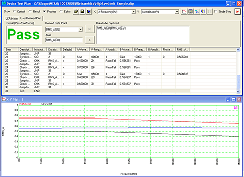
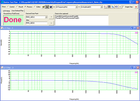
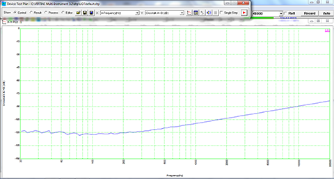
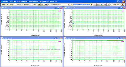
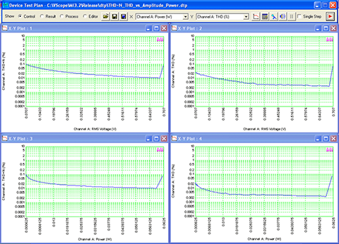
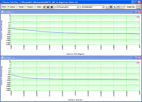
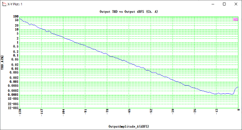
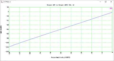
- Test results (e.g. Gain vs Frequency, Phase vs Frequency, etc.) can be plotted in up to 8 X-Y plots and reported in one textual log window called Device Test Plan Log in real time. The data in X-Y Plots can be exported as TXT files or copied into the clipboard as text and later pasted into other software such as Microsoft Excel for further analysis. The graph of the X-Y plot can be copied into the clipboard as Bitmap image and later pasted into other software such as Microsoft Word. The graphs can also be printed out directly or exported as BMP files. The data in the Device Test Plan Log can be saved as a TXT file.
- Support batch file processing and batch signal event capturing and storing.
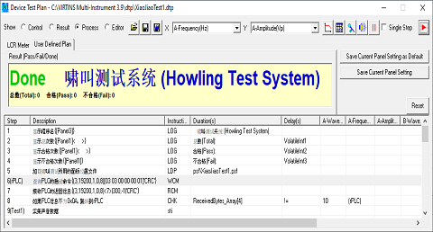
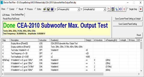
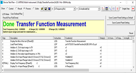
- A device test plan can be created, edited, modified, saved, locked, reloaded, executed.
- There are two types of device test plans: locked and unlocked. A locked device test plan cannot be modified within the software after it has been created.
- Support Pass/Fail check. Support connection with external systems through serial communication.
- Supports Multilingual User Interface under Windows 2000, XP, Vista, 7, 8, 8.1, 10, 11 and above. Currently supported languages are English, French, German, Italian, Portuguese, Spanish, Russian, Simplified Chinese, Traditional Chinese, Japanese and Korean.
Examples
×
![]()