Page 1 of 1

Sensor CA-YD-185 for soundboard testing

PostPosted: Fri Nov 23, 2018 7:57 am
by Josephus
Can that probe (sensor CA-YD-185) be used with an adapter to a microphone input on a computer sound-card with an external power supply?

Would the multi-meter or data logger display the data.

Would it be appropriate to use for measuring soundboard movements: acceleration, velocity, displacement in real time on a guitar top for example.

If so can a demonstration be done and posted on this forum or a video made as you did for the speed of sound?

Thank you. Joseph

Re: Sensor CA-YD-185 for soundboard testing

PostPosted: Sun Nov 25, 2018 4:14 am
by VirtinsTech
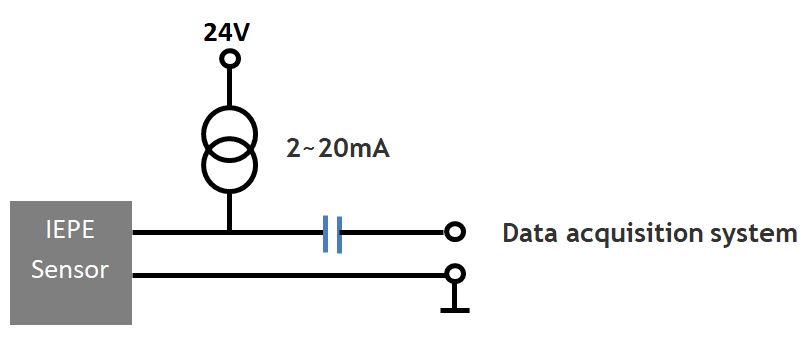
CA-YD-185 is an IEPE accelerometer. It requires a 24V 4mA excitation power supply as shown below. You can use an external 24V 4mA constant current power supply to drive an IEPE sensor, and feed its output to an AC coupled data acquisition system such as a sound card or a VT USB DSO. You can also use our product VT IEPE-2G05 which already has built-in 24V 4mA power supplies to excite the IEPE sensors.
1.png
1.png (9.83 KiB) Viewed 120488 times


IEPE sensors come with a factory-calibrated unit-specific sensor sensitivity. For example, an IEPE accelerometer may have a sensor sensitivity of 50 mV/g. If the data acquisition system is already voltage calibrated, such as a VT USB DSO or VT IEPE-2G05, then the acquired data can be converted from absolute voltage to absolute acceleration by software. Absolute velocity and displacement can then be derived through integration. Unfortunately, a sound card is usually not voltage calibrated, therefore, it can only perform relative amplitude measurement unless the users calibrate the absolute voltage by themselves. Depending on the output voltage of the IEPE sensor during measurement, either mic input or line input of a sound card can be used.

Some sound cards have XLR mic inputs with built-in 48V phantom power supplies. On the 48V pin, there is an internal current limiting resistor in series which would limit the current to be less than 20mA even if it is shorted to GND. If the IEPE sensor is able to withstand 48V, then an easy and workable solution (admittedly not very professional) is available as follows. In this way, the external 24V 4mA constant current power supply is not needed.

2.png
2.png (27.18 KiB) Viewed 120488 times


In addition to the electrical interface compatibility, the following parameters need to be considered when judging whether CA-YD-185 is suitable for measuring soundboard movement:

1. Frequency Measurement Range of the sensor
2. Size and weight of the sensor
3. Mounting methods (adhesive, stud, screw, magnetic)

If the sound board to be measured is big and heavy and you have a good way to mount it, CA-YD-185 is probably OK. Otherwise, CA-YD-160 would be better, as it is much lighter and smaller. It can be mounted using adhesive.

In case CA-YD-160 is still too heavy and too big, then piezo film sensors can be considered.

Re: Sensor CA-YD-185 for soundboard testing

PostPosted: Tue Nov 27, 2018 4:22 am
by Josephus
Thank you for your detailed answers. I will study them including the options your suggested re: piezo film sensors and CA-YD-160 and how to use them during a manufacturing process.
Much appreciated.
Joseph

Re: Sensor CA-YD-185 for soundboard testing

PostPosted: Thu Jul 30, 2020 2:28 am
by Josephus
I am exploring the option you provided me a couple of years ago for the sensor CA-YD-160 instead of the CA-YD-185.
I could not estimate the minimum displacement the sensor could detect. Ideally for a harp soundboard that would in sub-microns from 0.01 microns to 100 microns. What voltage range would it register for those oscillations?
Also would 24v source from a computer power supply be acceptable for the power source. What would you suggest otherwise.

Thank you for your support
Joseph

Re: Sensor CA-YD-185 for soundboard testing

PostPosted: Thu Jul 30, 2020 7:23 pm
by VirtinsTech
CA-YD-160 is an accelerometer. It does not measure displacement directly. In Multi-Instrument, an acceleration signal can be converted to a velocity signal and then a displacement signal through single integration and double integration. The following shows a simulated 1kHz sinewave with a peak acceleration of 1 g. It can be seen the measured peak velocity is 1.57 mm/s, and the measured peak-to-peak displacement is 0.524 um.

A.png
Acceleration
A.png (48.5 KiB) Viewed 100846 times

(Acceleration)


V.png
Velocity
V.png (50.32 KiB) Viewed 100846 times

(Velocity)


D.png
Displacement
D.png (51.41 KiB) Viewed 100846 times

(Displacement)

The IEPE sensor requires 24V 4mA constant current power supply (not a 24V constant voltage power supply) as shown in the previous posting. Measurement of absolute acceleration, velocity and displacement require voltage measurement being calibrated. These requirements need to be satisfied when using a sound card to interface to a IEPE sensor. Alternatively, VT IEPE-2G05 can be directly used with any IEPE sensors.